
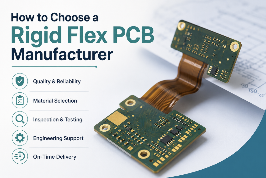

Modern electronic products continue to demand lighter, smaller, and more reliable designs without sacrificing performance. From medical equipment and aerospace systems to industrial controls and wearable technology, rigid flex printed circuit boards have become an effective solution for integrating complex circuits into compact mechanical assemblies.
Choosing the right manufacturing partner, however, requires more than comparing prices or reviewing advertised capabilities. Rigid flex fabrication combines rigid and flexible materials within a single circuit, introducing unique manufacturing challenges that are not encountered in conventional PCB production. Material selection, lamination methods, bend reliability, and inspection procedures all play an important role in the final product quality.
Selecting the best rigid flex PCB manufacturer begins with understanding how a supplier manages these technical requirements throughout design review, fabrication, and quality control. This guide explains the most important factors engineers and procurement teams should evaluate before selecting a manufacturing partner.
Evaluate Experience with Rigid Flex Manufacturing
Rigid flex PCBs require considerably more process control than standard multilayer boards. A manufacturer may have extensive experience producing rigid PCBs while having only limited expertise with rigid flex constructions.
Rather than asking whether a supplier can manufacture rigid flex boards, ask about their experience with projects involving:
- Multilayer rigid flex structures
- Dynamic and static bend applications
- Complex stackups
- High-density interconnections
- Controlled impedance designs
- Prototype and production fabrication
Suppliers that routinely manufacture rigid flex boards are generally better equipped to identify potential fabrication issues during the Design for Manufacturability review.
Review Material Selection and Flex Core Construction
Material selection has a direct impact on bend reliability, thermal stability, and manufacturing consistency.
The flexible section of a rigid flex PCB is typically constructed using polyimide, while rigid areas commonly use FR-4 laminates. These materials must function together as a complete system rather than as separate components.
During supplier evaluation, discuss:
- Polyimide flex core options
- Core thickness selection
- Material compatibility
- Thermal performance
- Dielectric requirements
- Stackup planning
An experienced manufacturer should explain how material selection affects both manufacturing yield and long-term product reliability.
Understand No Flow Prepreg Requirements
One important aspect of rigid flex manufacturing is the use of no flow prepreg.
Unlike conventional prepreg materials, no flow prepreg is designed to minimise resin movement during lamination. This helps preserve cavity dimensions and prevents excess resin from entering flexible regions where unrestricted movement is required.
Manufacturers should explain:
- When no flow prepreg is appropriate
- Lamination process control
- Resin management
- Material compatibility
- Manufacturing limitations
Proper use of no flow prepreg contributes to improved dimensional stability and more reliable rigid-to-flex transitions during fabrication.
Evaluate Coverlay Materials
Flexible circuits do not normally use traditional solder mask within bending areas.
Instead, they rely on coverlay, which protects copper conductors while maintaining flexibility.
When discussing manufacturing capability, ask about:
- Coverlay material options
- Coverlay thickness
- Opening tolerances
- Pad definition
- Adhesion performance
- Long-term durability
Well-controlled coverlay lamination helps protect flexible conductors against mechanical stress, moisture, and repeated bending while supporting reliable assembly processes.
Rolled Annealed vs Electrodeposited Copper
Copper foil selection has a significant influence on flex performance.
The two most common options are:
Rolled Annealed Copper
Rolled annealed (RA) copper offers greater ductility, making it better suited for applications involving repeated bending or dynamic flexing.
Advantages include:
- Improved bend endurance
- Reduced cracking risk
- Better fatigue resistance
- Longer service life
Electrodeposited Copper
Electrodeposited (ED) copper is widely used in conventional rigid PCBs and may be appropriate for static or limited-bend applications.
While ED copper can perform well in many designs, it generally offers lower flex endurance than RA copper in dynamic applications.
Understanding which copper type a manufacturer recommends—and why—can provide valuable insight into their engineering expertise.
Assess the Rigid-to-Flex Transition Design
The transition between rigid and flexible sections is one of the most critical areas of a rigid flex PCB.
Mechanical stress is often concentrated at this interface, making careful design and manufacturing essential.
Ask suppliers how they address:
- Transition geometry
- Stress reduction
- Copper anchoring
- Via placement
- Layer alignment
- Bend radius recommendations
Manufacturers with proven rigid flex experience typically incorporate design practices that minimise stress concentration while improving long-term reliability.
Review Stiffener Design and Integration
Stiffeners strengthen selected areas of a flexible circuit, particularly around connectors, components, and assembly locations.
Common stiffener materials include:
- FR-4
- Polyimide
- Stainless steel
A capable manufacturer should discuss:
- Stiffener material selection
- Thickness recommendations
- Adhesive systems
- Assembly considerations
- Mechanical reinforcement
Proper stiffener integration improves handling during assembly while reducing stress around connector regions and surface-mounted components.
Supplier Evaluation Checklist
Before requesting quotations, evaluate manufacturers using measurable technical criteria.
| Evaluation Area | Questions to Ask |
| Manufacturing Experience | How many rigid flex projects are produced each year? |
| Flex Core Materials | Which polyimide constructions are supported? |
| No Flow Prepreg | How is resin controlled during lamination? |
| Coverlay | Which coverlay systems are routinely used? |
| Copper Type | When is RA or ED copper recommended? |
| Transition Design | How are rigid-to-flex stress areas engineered? |
| Stiffeners | Which materials and thicknesses are available? |
| Inspection | What verification methods are performed during fabrication? |
Inspection and Quality Verification
Rigid flex PCBs require comprehensive inspection throughout fabrication because defects may develop within internal layers or at rigid to flex transition areas where they are difficult to detect after assembly.
Rather than relying solely on final inspection, experienced manufacturers perform verification at multiple stages of production.
Common inspection methods include:
- Automated Optical Inspection (AOI)
- X ray inspection for multilayer alignment
- Cross section analysis
- Electrical continuity testing
- Dimensional verification
- Visual inspection of coverlay application
- Lamination quality assessment
Cross section analysis is particularly valuable because it allows engineers to verify copper plating, layer alignment, dielectric thickness, and the quality of rigid to flex transitions without relying on external visual inspection alone.
A supplier should be able to explain how these inspection methods fit into its manufacturing workflow rather than simply listing available equipment.
Design for Manufacturability Review
Many rigid flex manufacturing challenges can be prevented during the engineering review stage.
A thorough Design for Manufacturability (DFM) review helps identify issues before fabrication begins, reducing engineering changes, production delays, and unnecessary costs.
Typical DFM topics include:
- Stackup optimisation
- Flex region dimensions
- Bend radius recommendations
- Coverlay openings
- Stiffener placement
- Copper balancing
- Component placement near bend areas
- Material compatibility
- Panel utilisation
Early collaboration between designers and manufacturers generally leads to more reliable products while improving production efficiency.
Bend Reliability and Long Term Performance
One of the primary advantages of rigid flex technology is its ability to replace connectors and cable assemblies while improving mechanical reliability.
However, bend performance depends on both good design practices and consistent manufacturing processes.
Manufacturers should evaluate factors such as:
- Bend radius
- Copper type
- Layer construction
- Coverlay integrity
- Transition geometry
- Material selection
- Mechanical stress distribution
Designs intended for repeated movement typically require different engineering considerations than products that remain in a fixed position after installation.
Matching the manufacturing process to the intended application helps improve long term reliability while reducing the risk of conductor fatigue or mechanical failure.
Prototype to Production Planning
A successful engineering prototype does not automatically guarantee a smooth transition into production.
As manufacturing volumes increase, process consistency becomes increasingly important.
Questions worth discussing with potential suppliers include:
- How are prototypes reviewed before release?
- What engineering documentation accompanies production?
- How are manufacturing changes controlled?
- Are inspection procedures consistent between prototype and production?
- How are process improvements documented?
Manufacturers with well established production control procedures are generally better positioned to maintain consistent quality throughout the product lifecycle.
Common Supplier Selection Mistakes
Engineering teams sometimes evaluate suppliers based primarily on price or advertised capability without considering long term manufacturing performance.
Common mistakes include:
- Choosing suppliers with limited rigid flex experience
- Overlooking material compatibility
- Ignoring DFM feedback
- Failing to review inspection procedures
- Selecting inappropriate copper foil for the application
- Underestimating the importance of transition design
- Not discussing prototype to production scalability
Avoiding these issues early in supplier selection often reduces engineering revisions and helps improve production yield.
Procurement Evaluation Checklist
Before selecting a rigid flex PCB manufacturing partner, engineering and purchasing teams should confirm that the supplier can demonstrate experience in the areas most critical to product reliability.
| Evaluation Area | Verification |
| Rigid flex manufacturing experience | Demonstrated production history |
| Flex core materials | Appropriate polyimide options available |
| No flow prepreg | Controlled lamination process |
| Coverlay application | Consistent protection of flex circuits |
| Copper selection | Suitable RA or ED copper recommendations |
| Transition design | Engineering review of stress areas |
| Stiffener integration | Material and placement guidance |
| Inspection | AOI, X ray, cross section, and electrical testing |
| DFM support | Engineering review before fabrication |
| Production scalability | Documented prototype to volume process |
Using a structured evaluation process helps procurement teams compare suppliers using measurable technical criteria instead of marketing claims.
Final Thoughts
Selecting a rigid flex PCB manufacturer involves much more than comparing fabrication capabilities or requesting quotations. Successful projects depend on choosing a manufacturing partner that understands the interaction between materials, stackup design, lamination processes, and long term mechanical reliability.
Engineering expertise in areas such as no flow prepreg, flex core construction, coverlay application, rigid to flex transition design, copper selection, stiffener integration, and comprehensive inspection can significantly influence manufacturing quality and product performance.
For organisations seeking an experienced partner, fast turn rigid flex PCB manufacturing services provide engineering support from Design for Manufacturability review through prototype fabrication and production. As with any complex PCB project, achievable lead times and manufacturing approaches should always be confirmed after reviewing the board design, material requirements, layer count, production quantity, and testing requirements.
A structured supplier evaluation process enables engineering and procurement teams to make informed decisions, reduce manufacturing risks, and improve the likelihood of delivering reliable rigid flex products throughout their operational lifetime.
